Device Integration Workspace
The Device Integration Workspace provides information on the UI components for creating drivers, networks, device connections, and so on.
The driver workspace displays the ID of the currently selected IEC61850 driver in the Drivers folder in the System Browser.
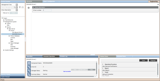
Driver Information | |
Item | Description |
Driver Number | Displays the ID of the selected IEC61850 driver. |
IEC61850 Toolbar | ||
Icon | Name | Description |
| Delete object | Deletes the IEC61850 driver. You can delete a driver as long as it is not associated with an existing network. However, if the selected driver is associated with a network, a message informs you that the driver cannot be deleted as it is monitoring a network. In this case, to delete the driver, you must first remove the network to which this driver is associated. |
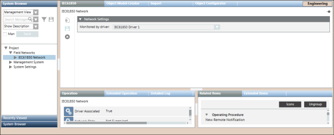
The IEC61850 Network workspace allows you to configure the network settings such as associating the IEC61850 driver to the network, saving the association, and deleting the network. The properties associated with the selected network display in the Operation or Extended Operation tab. You can also change the value of the poll interval. By default, this value is set to 0 ms.
IEC61850 Toolbar | ||
Icon | Name | Description |
| New IEC61850 Connection | Creates a new Device Connection. |
| Save data | Saves any changes. |
| Delete object | Deletes the IEC61850 network. |
Network Settings Expander
The Network Settings expander allows you to define the IEC61850 Driver monitoring for a IEC61850 network.
Network Settings | |
Item | Description |
Monitored by driver | Allows you to select an IEC61850 driver. |
The Object Model Creator Workspace allows you to design object models from the online or offline methods.

Item | Description |
Select SCL File | Displays the selected Substation Configuration Language (SCL) file. |
Browse | Allows you to specify the path of the SCL file. The SCL file can have either of the following extensions, .cid, .icd, .iid, or .scd. |
Load elements | Displays the information of the IEC61850 device objects and their associated properties in a tree structure in the IEC objects list. |
Selected properties | Displays the folder structure for the grouping of related properties of the object model and other columns such as Property Name, Direction, IEC Attribute, and Type. |
Add Folder | Allows you to create a new folder to drag the leaf nodes from the tree structure in the IEC Objects list. |
Property Name | A unique name for the property |
Direction | Direction of the property |
Add command | Displays fields to specify the details of the command properties of the device. |
Command Folder Name | Folder name under which the device command properties are to be added. For example, if you want to issue commands to properties of a circuit breaker, then you can specify the name as Circuit_Breaker_Device. |
Command Name | Name of the command property of the device for which you want to trigger the command. For example, if you want to trigger the open and close command for a circuit breaker on a name property, then specify Name in the Command Name field. |
Command Description | Description of the device property for which you want to trigger the command. |
Command Attribute | Control property of the device for which you want to trigger a command. You must drag and drop the control property from the IEC objects section. |
Status Attribute | Status property of the device for which you want to trigger a command. You must drag and drop the control property from the IEC objects section. |
Control Model | Select the type of commanding from any of the following options for the device: Direct: Command for the device property can be executed via Direct Mode without selecting the object first |
Library name | Name of the IEC61850 library. You must drag the library object from the System Browser. |
Object model name | Name of the object model to be designed |
Create object model | Creates the object model with the specified details. |
The IEC61850 Importer allows you to manage the import of field data (engineering objects) described in IEC configuration files (CSV file).
You can import the field data (engineering objects) described in IEC configuration files (CSV file) from the IEC61850 Device Importer Workspace.

NOTE:
Power Devices must be integrated in Desigo CC only by the Powermanager extension.
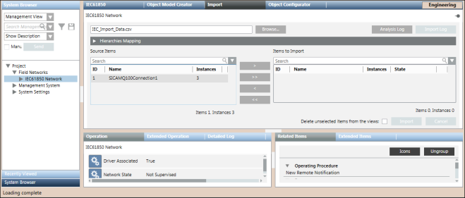
Import Fields | |
Item | Description |
Browse | Displays the Open dialog box and allows you to select a file to import. The path of the selected file appears in the field. |
Source Items | Displays a preview all the objects available in the selected CSV file. These objects are identified by the following:
|
Imported Items | Displays a preview of all the objects selected for import. These objects are identified by the following:
NOTE: |
Search | Allows you to apply a search filter to the content that displays in the Source Items or Imported Items list. |
Delete unselected items from views | Allows you to specify whether or not, during the import, all the items available in the views, but not present in the file to import, must be deleted. If you check this option, any items relevant to the objects are also deleted (text groups included). NOTE: |
Import | Starts the import process. NOTE: |
Cancel | Aborts the import process. NOTE: |
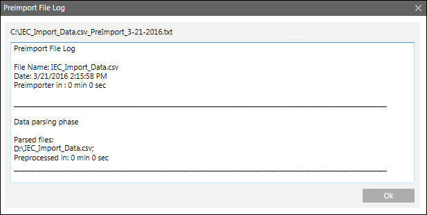
Analysis Log | Displays the Preimport File Log dialog box with the errors encountered during pre-processing phase of the CSV file. NOTE: |
Import Log | Displays the Import File Log dialog box with the details of the import process. NOTE: |
Preimport File Log
You can view the errors encountered during the pre-processing of the CSV file from the Preimport File Log dialog box that displays by clicking the Analysis Log button available above the Items to Import field. This Analysis Log button is enabled only when the pre-processing is complete.
Import File Log
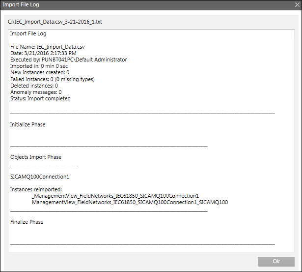
You can view the errors encountered during the import of the Device Connections and Logical Devices from the Import File Log dialog box that is displayed by clicking the Open Log button above the Items to Import field. This button is enabled only when the import is complete.
Hierarchies Mapping Expander
Once you have extracted a CSV file to import, the Hierarchies Mapping expander allows you to define the root node for each hierarchy and for each System Browser view.
The Hierarchies Mapping expander allows you to configure the destination in the system views of the data structures (hierarchies) imported according to the Import Rules.

Hierarchies Mapping Expander Fields | |
Item | Description |
Hierarchy Name | Displays the hierarchy name. |
Import this hierarchy under this node | Displays the hierarchy import rule (for example, the Hardware hierarchy was assigned to the Management View). For the logical and user-defined views, you must assign the desired root node. To do this, select the view from the System Browser drop-down list, and drag the view root node to the suggested field. |
The IEC61850 Device Connection Workspace allows you to view the objects and properties of the IEC61850 devices that are connected to your system and also provides options to create an Object Model for the IEC61850 devices. In the hierarchy of the System Browser tree, each IEC61850 network contains a set of IEC61850 device connections. In turn, each IEC61850 device connection contains the logical devices attached to that connection.

Device Connection Expander
In Engineering mode, when you select an IEC61850 device connection in the System Browser, its settings display in the Device Connection expander in the IEC61850 tab. You can save the data or delete the IEC61850 device connection using the options available in the toolbar.
IEC61850 Toolbar | ||
Icon | Name | Description |
| Save data | Saves any changes. |
| Delete | Deletes the current object. |
Device Connection Expander Fields | |
Item | Description |
Connection name | Displays the name of the Device Connection object. This is a read only field. |
Connection description | Displays the description of the Device Connection object. This is a read only field. |
TCP port | Displays the TCP port number assigned to the device in the network. You can modify this field. |
IP address | Displays the hardware address of a device connected to a network that uses Internet Protocol (IP) for communication. You can modify this field. |
Browse Expander
The Browse expander lists the objects and properties of the IEC61850 devices that are connected to your system. It also provides options to create an Object Model for the IEC61850 devices without having to create a CSV file. For more information, see Designing the Object Model by Browsing an Online IEC 61850 Device.
Browse Expander Fields | |
Item | Description |
Discover objects (For Designing the object model by browsing an online IEC61850 device) | Prefills the IEC Objects list with the list of objects in the IEC61850 devices connected to your system. The Selected Properties section displays the folder structure for the grouping of related properties of the object models and other columns such as Property Name, Direction, IEC Attribute, and Type. |
Load Elements (For Designing the object model by the offline method) | Prefills the IEC Objects list with the list of objects in the IEC61850 devices connected to your system. The Selected Properties section displays the folder structure for the grouping of related properties of the object models and other columns such as Property Name, Direction, IEC Attribute, and Type. |
IEC Objects | List of IEC61850 objects of the IEC61850 devices connected to your system. |
Selected Properties | Displays the properties of the object selected in the IEC Objects list along with the folder structure under which these properties can be grouped. |
Add Folder | Adds a new folder to the existing folder structure or allows you to create a new folder structure. |
Add command | Displays fields to specify the details of the command properties of the device. |
Command Folder Name | Folder name under which the device command properties are to be added. For example, if you want to issue commands to properties of a circuit breaker, then you can specify the name as Circuit_Breaker_Device. |
Command Name | Name of the command property of the device for which you want to trigger the command. For example, if you want to trigger the open and close command for a circuit breaker on a name property, then specify Name in the Command Name field. |
Command Description | Description of the device property for which you want to trigger the command. |
Command Attribute | Control property of the device for which you want to trigger a command. You must drag and drop the control property from the IEC objects section. |
Status Attribute | Status property of the device for which you want to trigger a command. You must drag and drop the control property from the IEC objects section. |
Control Model | Select the type of commanding from any of the following options for the device: Direct: Command for the device property can be executed via Direct Mode without selecting the object first |
Library name | Name of the IEC61850 library. You must drag the IEC61850 library object from the System Browser to the Library name field. |
Object model name | Name of the IEC61850 Object model to be created. |
Create object model | Creates the IEC61850 Object Model and Import Rules. |
The connectivity and communication between the IEC61850 devices and the IEC61850 Driver depends on the values of properties that are set for a Device Connection object. After successfully importing the IEC61850 CSV file, the Device Connection object is created and the default values of its properties display in the Extended Operation pane. For a successful communication between the IEC61850 devices and the IEC61850 Driver, you must ensure the following:
- The IEC61850 devices and IEC61850 Driver are connected if the properties such as, client AP Title and Server AP Title, Client PSEL and Server PSEL, Client SSEL and Server SSEL, and client TSEL and Server TSEL are identical and are set to their default values.
- If the value of the client or server version of a property (for example, Client AP Title or Server AP Title) changes to a value other than the default value, then the device is disconnected.
- The devices continue to be in the connected state if the value of the client or server version of the properties such as, Use Client Invoke Settings and Use Server Invoke Settings, and Use Client Title Qualifier Settings and Use Server Title Qualifier Settings are changed to a value other than the default value and are identical. For example, if the Use Client Invoke Settings property is set to
Disabled, then the Use Server Invoke Settings must also be set toDisabled. - You must compare the property values of the Device Connection object that are displayed in the Extended Operation pane with the property values in the Substation Configuration Language (SCL) file of the IEC61850 device. If the property values in the SCL file are different, then they must be updated from the Extended Operation pane.
When re-importing IEC61850 data in Logical and User Defined Views using a CSV file, the re-import applies only to the IEC61850 logical devices referred to in the CSV file.
The re-import operation is done in a similar way as the import, except that the existing IEC61850 logical device objects are updated as follows:
- The new logical device entries in the CSV file are added to the existing logical device entries in the System Browser, if the Delete unselected items from the views check box is not selected.
- If the device description of a logical device is modified in the CSV file, with no change to the existing paths of LogicalHierarchy or UserDefinedHierarchy, then the existing device description of the logical device is updated with the new description, if the Delete unselected items from the views check box is not selected.
- If the device name or device description of a logical device is modified in the CSV file, with no change to the existing LogicalHierarchy or UserDefinedHierarchy paths, then the modified device nodes are added as siblings of the existing logical device nodes in the System Browser, as long as the Delete unselected items from the views check box is not selected.
- If the device name or device description of a logical device is modified in the CSV file, with no change to the existing paths LogicalHierarchy or UserDefinedHierarchy paths, andthe Delete unselected items from the views check box is selected, then the existing logical device nodes below the hierarchy path are deleted and the device nodes in the CSV file are added. In this case, only the logical device nodes are deleted; the hierarchy paths are not deleted.
- If the device name or device description of a logical device is modified in the CSV file, the existing path of LogicalHierarchy or UserDefinedHierarchy is modified, and the Delete unselected items from the views check box is selected, then the existing device nodes below the previous hierarchy path are deleted and the device nodes with new hierarchy paths in the CSV are added. In this case, only the logical device nodes are deleted; the hierarchy paths are not deleted.
- If the existing LogicalHierarchy or UserDefinedHierarchy path is modified in the CSV file, the Delete unselected items from the views check box is selected, and there no change to the device name or device description, then the existing device nodes below the previous hierarchy path remains unchanged and the device nodes with new hierarchy paths in the CSV are added.
- A logical device, for example, IEC61850 device1 associated with Device Connection IEC61850 Device Connection 1 is present in the logical view. On re-import, if there is no change to the name of the logical device entry in the CSV file, but the name of the Device Connection changes to IEC61850 Device Connection 3. In this case, #1 will be appended to the logical device name of the second entry in a logical view or user defined view. On subsequent re-imports, the number equivalent to #n+1 is appended to the logical device name.
In situations where there are two device nodes with the same names, the Importer performs the parsing operation using any of the following methods:
- If a node with the same name does not exist, then the node is created.
- If a node with the same name referring to the same data point exists, then only the description is updated.
- If a node with the same name referring to a different data point exists, then a new node with name_#n is created.
When re-importing IEC61850 data using a CSV file, the re-import applies to the IEC61850 device connections and logical devices referred to in the CSV file. The re-import operation is done in a similar way as the import, except that the pre-existing IEC61850 objects are updated as follows:
- Creating new device connections and logical devices.
- Updating existing device connections and logical devices.
- Deleting existing device connections and logical devices (only if the Delete unselected items from the Views check box is selected). Deleting the IEC61850 device connections and logical devices results in deleting them from all the hierarchies in other views.
This operation also causes the Management View hierarchy to update with any new objects that are added or removed from the CSV file.
The import process deletes any IEC61850 device connections and logical devices that are no longer present in the CSV file (only if the Delete unselected items from the views check box is selected).
During re-import, the IEC Importer prevents changing an already imported IEC logical device in the Object Model (OM) instance. For example, during import, if an instance of an IEC_Device Object Model is created with the name IEC_Device_1, then the Importer will report an error if you specify an instance with the same name (IEC_Device_1). but with a different Object Model during re-import.
Re-Importing Alias Information
The following information with respect to re-importing the data from the Alias column of the CSV file applies when re-importing objects from any of the views (physical, logical, user-defined).
- If the alias information in the IEC61850 CSV file is not assigned to any node in the system, then the alias can be assigned to the IEC61850 Device Instance node or IEC61850 Logical Device node.
- If the alias information in the IEC61850 CSV file is assigned to any node in the system, then the system checks to see if the name of the node to which the alias is assigned and the name of the node associated with the IEC61850 Device Instance or IEC61850 Logical Device are identical or different. If both nodes have identical names, then the alias information is imported. However, if the names of both the nodes are different, then the alias information is not imported since the same alias cannot be assigned to two nodes in the system. In this situation, a message informing you the reason for the import failure displays in the Preimport Log File dialog box.
The management station monitors the number of IEC61850 objects in the system to ensure that the total count of these objects does not exceed the defined limits for the total number of system objects. The monitoring is done using properties such as System Objects Limit, System Load, System Objects, and Notification Threshold. These properties display in the Extended Operations tab when you select the Main Server Object from the Management View. Depending on the situation, the management station will perform any of the following:
- Issue warnings when you are approaching the maximum permitted limit.
- Generate an alarm if the System objects exceed the maximum permitted limit.
- Prevent importing IEC61850 objects if the import activity can cause the system objects to exceed the maximum permitted limit.
The maximum permitted limit is defined by the System Objects Limit property.
The following scenarios provide a better understanding of the monitoring activity:
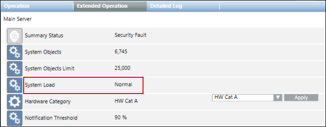
If the number of IEC61850 objects is below both the system limits (defined by the System Objects Limit property) and the safety threshold (defined by the Notification Threshold property), then the System Load property indicates Normal and displays in the Extended Operation tab only.
NOTE: If you want to import IEC61850 device connections or logical devices, the system will permit an import only if the System Objects Limit property and Notification Threshold property do not exceed their defined limits.
- If the number of IEC61850 objects is between the system limits (defined by the System Objects Limit property) and the safety threshold (defined by the Notification Threshold property), then the System Load property indicates Warning and displays in the Extended Operation tab.
NOTE: In case of an import operation that exceeds the safety threshold, a warning message informs you how close you are to the limit (for example, 90%) and you can then decide whether or not to proceed with the import. 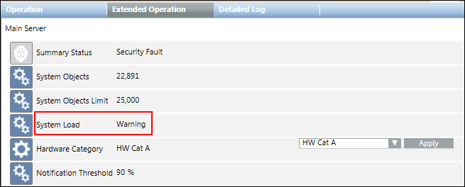

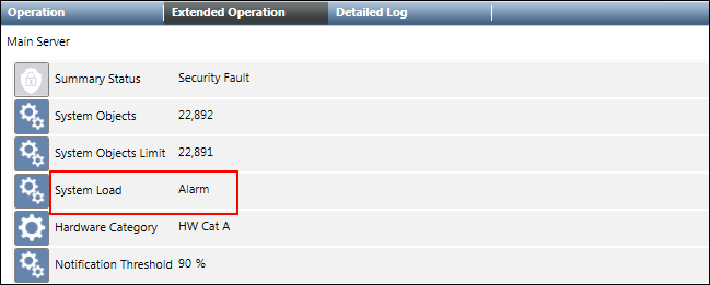
- If the number of IEC61850 objects exceeds the system limits (defined by the System Objects Limit property), then the System Load property indicates Alarm and displays in the Extended Operation tab.
NOTE: If an import operation exceeds the system limits, an error message displays to inform you that the import will not start.


With Desigo CC V5.1, the IEC61850 connection objectmodel, 'GMS_IEC61850_Connection', which uses the internal DPT '_IEC61850_IED' provided by WinCCOA Platform is replaced with a new objectmodel 'GMS_IEC61850_Connection_1' which is an exact replica of '_IEC61850_IED'. The instances of GMS_IEC61850_Connection created in projects till V5.0 will be upgraded automatically to 'GMS_IEC61850_Connection_1' in V5.1 and later versions without any user intervention.
The object model upgrade process is triggered automatically when you upgrade your project to V5.1 and start the project for the first time in SMC. The upgrade process is triggered only when the drivers monitoring the old IEC61850 connection instances are in either the 'Started' or 'Configuration' states. If the drivers are not in either of the states, the system will monitor the driver's state after periodic time intervals.
If the upgrade process fails due to certain reasons, there will be two or more retries to upgrade the failed instances. The logs related to success and failure will be logged in a file located at <ProjectFolder>/log/IECConnectionOMUpgrade_Log_<TimeStampValue>.
If the upgrade process is not triggered automatically or fails at some point after multiple retries, then in order to trigger the upgrade process again, you must restart the project with a valid IEC61850 license and all the IEC drivers must be in either the 'Started' or 'Configuration' states. You can identify a failure in the upgrade process or a failure to trigger the upgrade process when you observe a loss of communication with field devices and thereafter checking the log file for such instances.


